Infrared Proximity Detector Alarm

 Infrared Proximity Detector Alarm Circuit Diagram:new high mini major
 Infrared Proximity Detector Alarm Circuit Diagram
This circuit can be built from readily available low-cost components, some of which may even be hiding in your junkbox! The indicated value of 22 Ω for resistor R1 causes an average current of about 65 mA through infrared emitter D1. Because the IRED is pulsed at a duty factor of about 50% through the action of T1 and IC1, a peak current of 128 mA flows during every half cycle. This may seem a lot but in fact is well within the safe specification of the LD274. The LM567 PLL IC is configured to supply a switching frequency of about 20 kHz. When the infrared beam emitted by D1 is reflected by a nearby object, IC1, through receiver diode D2 and transistor T2, receives the recovered 20 kHz signal at its input, pin 3. Because the ‘567 PLL is then locked, the IC output (pin 8), drops low, triggering the 555 chip in monostable mode (IC2) and so causing acoustic actuator Bz1 to sound. The monostable remains on as long as the reflected signal is being received. Because of the presence of T3, capacitor C5 is allowed to charge only when no signal is being received. In that condition, the 555 is turned off automatically after a time determined by R9-C5. Using the component values shown, this will be about 5 seconds. Obviously D1 and D2 should be mounted such that the latter can only pick up reflected infrared light.

The choice of the two infrared components used in this circuit will be uncritical but they must be ‘band’ compatible, i.e., generate (D1) and respond to (D2) the same wavelength. The operating point of the receiver input circuit is rather dependent on ambient day-light levels and the value of R4 may need to be adjusted a little to ensure a voltage of between 1.5 V and 4 V on the collector of T1 when no signal is being received. Some dc buzzers cause a lot of back-emf so it may be necessary to insert a diode in series with the output of IC1. If necessary, this diode should preferably be a Schottky type because of the inherent low voltage drop of about 0.4 V as opposed to 0.65 V for a typical small-signal silicon diode.

Rain Director / Water Sensor

sensor water rain project main mini ieee latest new electronics seminar google
Water is a conductor of electricity. When water is in contact with the probe then there is a flow of current toward the base of  NPN transistor (BC548), which conducts. With the conduction of NPN transistor, electron reaches to Q2, which is a PNP transistor . PNP transistor (BC558) also conducts and current flows through the speaker. In a speaker there is inductive coil which causes motion in one direction and after that produces induce current, which is in opposite direction to the flow of current this induced current in the form of pulse, flows through a capacitor, resistance and makes 1st transistor BC548 off for an inter-well and after-that it relaxes to previous state. This process repeats again and again till probe is in contact with water and an oscillation is created in the circuit. Speaker diaphragm vibrates and gives a tone. Frequency of the circuit depends on the value of Coil impendence, Capacitor and Resistance Value.

Petrol/Diesel Level Sensor

This sensor is particularly suitable for use in small spaces, such as the petrol tank of a  motorbike. It has the advantage of not having any moving parts, unlike a conventional sensor with a float and float arm that make it difficult to fit in a tank.

The sensor circuit is made from standard, inexpensive components and can be put together for little money.
Petrol/Diesel Level Sensor latest new project ieee electronics instrumentation


The operating principle is  based on  measuring  the forward volt-ages of two identical diodes (check this  first by measuring  them).  The forward voltage of a diode decreases with increasing junction temperature. lf a resistor is placed close to one of the two diodes, it will be heated slightly if it extends above the surface of the  petrol. For best results,the other diode (used for reference) should be located at the same level. lf the diodes are covered by the petrol in the tank, the heating resistor will not have any effect because it will be cooled by the petrol. An opamp compares the voltage across the two diodes, with a slightly smaller current passing through the reference diode. 
a
When the petrol level drops, the output of the opamp goes high and the output transistor switches on. This causes a sense resistor to be connected in parallel with the sensor output. Several sensor circuits can be used together, each with its own switched sense resistor connected in parallel with the output, and the resulting output  signal can be used to drive a meter or the like.

Using this approach, the author built a petrol tank' sensors trip' tank consisting of five PCBs, each fitted with two sensor circuits. With this sensor strip installed at an angle in the tank, a resolution of approximately 1.5 litre per sensor is possible. Many tanks have an electrical fitting near the bottom for connection to a lamp on the instrument panel that indicates the reserve level. The sensor strip can be used in its place. You will have to experiment a bit with the values of the sense resistors, but do not use values lower than around'100 O. It is also important to fit the diodes and heater resistor in a little tube with a small opening at the bottom so that splashing petrol does not cool the heater resistor, since this would result in false readings.

The circuit should be powered from a regulated supply voltage of 5 to 6 V to prevent the heating resistors from becoming too hot. After testing everything to be sure that it works properly, it's a good idea to coat the circuit board with epoxy glue to provide better protection against the petrol.

Tip: you can use the well-known 1M3914 to build a LED display with ten LEDs, which can serve as a level indicator. Several examples of suitable circuits can be found in back issues of Elektor.

Note: this sensor circuit is not suitable for use in conductive liquids.

Automatic Street Light

An introduction:
Needs no manual operation for switching ON and OFF. When there is need of light it automatically switches ON. When darkness rises to a certain value then sensor circuit gets activated and switches ON and when there is other source of light i.e. day time, the street light gets OFF. The sensitiveness of the street light can also be adjusted. In our project we have used four L.E.D for indication of bulb but for high power switching one can connect Relay (electromagnetic switch) at the output of pin 3 of I.C 555. Then it will be possible to turn ON/OFF any electrical appliances connected all the way through relay.


Principle :
This circuit uses a popular timer I.C 555. I.C 555 is connected as comparator with pin-6 connected with positive rail, the output goes high(1) when the trigger pin 2 is at lower then 1/3rd level of the supply voltage. Conversely the output goes low (0) when it is above 1/3rd level. So small change in the voltage of pin-2 is enough to change the level of output (pin-3) from 1 to 0 and 0 to 1. The output has only two states high and low and can not remain in any intermediate stage. It is powered by a 6V battery for portable use. The circuit is economic in power consumption. Pin 4, 6 and 8 is connected to the positive supply and pin 1 is grounded. To detect the present of an object we have used LDR and a source of light.
LDR is a special type of resistance whose value depends on the brightness of the light which is falling on it. It has resistance of about 1 mega ohm when in total darkness, but a resistance of only about 5k ohms when brightness illuminated. It responds to a large part of light spectrum. We have made a potential divider circuit with LDR and 100K variable resistance connected in series. We know that voltage is directly proportional to conductance so more voltage we will get from this divider when LDR is getting light and low voltage in darkness. This divided voltage is given to pin 2 of IC 555. Variable resistance is so adjusted that it crosses potential of 1/3rd in brightness and fall below 1/3rd in darkness.
Sensitiveness can be adjusted by this variable resistance. As soon as LDR gets dark the voltage of pin 2 drops 1/3rd of the supply voltage and pin 3 gets high and LED or buzzer which is connected to the output gets activated.
Component used :
  1. 9v Battery with strip
  2. Switch
  3. L.D.R (Light Depending Resistance)
  4. I.C NE555 with Base
  5. L.E.D (Light Emitting Diode) 3 to 6 pieces.
  6. Variable Resistance of 47 KΩ
  7. P.C.B (Printed Circuit Board of 555 or Vero board.


COMPONENTS :
a) Battery: For 9v power supply we can use 6pcs dry cell or 6F22 9v single piece battery.
b)Switch:Any general purpose switch can be used. Switch is used as circuit breaker.
c) L.D.R: (Light Depending Resistance)
it is a special type of resistance whose value depends on the brightness of light which is falling on it. It has resistance of about 1mega ohm when in total darkness, but a resistance of only about 5k ohms when brightness illuminated. It responds to a large part of light spectrum.
d) L.E.D: (Light Emitting Diode)
A diode is a component that only allows electricity to flow one way. It can be thought as a sort of one way street for electrons. Because of this characteristic, diode are used to transform or rectify AC voltage into a DC voltage. Diodes have two connections, an anode and a cathode. The cathode is the end on the schematic with the point of the triangle pointing towards a line. In other words, the triangle points toward that cathode. The anode is, of course, the opposite end. Current flows from the anode to the cathode.
Light emitting diodes, or LEDs, differ from regular diodes in that when a voltage is applied, they emit light. This light can be red (most common), green, yellow, orange, blue (not very common), or infa red. LEDs are used as indicators, transmitters, etc. Most likely, a LED will never burn out like a regular lamp will and requires many times less current. Because LEDs act like regular diodes and will form a short if connected between + and -, a current limiting resistor is used to prevent that very thing. LEDs may or may not be drawn with the circle surrounding them.
e) Variable resistance: (Potentiometer)
Resistors are one of the most common electronic components. A resistor is a device that limits, or resists current. The current limiting ability or resistance is measured in ohms, represented by the Greek symbol Omega. Variable resistors (also called potentiometers or just “pots”) are resistors that have a variable resistance. You adjust the resistance by turning a shaft. This shaft moves a wiper across the actual resistor element. By changing the amounts of resistor between the wiper connection and the connection (s) to the resistor element, you can change the resistance. You will often see the resistance of resistors written with K (kilohms) after the number value. This means that there are that many thousands of ohms. For example, 1K is 1000 ohm,2K is 2000 ohm, 3.3K is 3300 ohm, etc. You may also see the suffix M (mega ohms). This simply means million. Resistors are also rated by their power handling capability. This is the amount of heat the resistor can take before it is destroyed. The power capability is measured in W (watts) Common wattages for variable
resistors are 1/8W, 1/4W, 1/2W and 1W. Anything of a higher wattage is referred to as a rheostat
f) PCB (Printed Circuit Board)
with the help of P.C.B it is easy to assemble circuit with neat and clean end products. P.C.B is made of Bakelite with surface pasted with copper track-layout. For each components leg, hole is made.
Connection pin is passed through the hole and is soldered.

automatic street light
Circuit Diagram

WORKING:
When light falls on the LDR then its resistance decreases which results in increase of the voltage at pin 2 of the IC 555. IC 555 has got comparator inbuilt, which compares between the input voltage from pin2 and 1/3rd of the power supply voltage. When input falls below 1/3rd then output is set high otherwise it is set low. Since in
brightness, input voltage rises so we
obtain no positive voltage at output of pin 3 to drive relay or LED, besides in poor light condition we get output to energize.

Precautions:
a) Use a Sensitive LDR. You can test it using a multimeter.
b) I.C should not be heated too much while soldering, excess heat can destroy it. For safety and easy to replace, use of I.C base is suggested. While placing the I.C pin no 1 should be made sure at right hole.
c) Opposite polarity of battery can destroy I.C so please check the polarity before switching ON the circuit. One should use diode in series with switch for safety since diode allows flowing current in one direction only.
d) L.E.D glows in forward bias only so incorrect polarity of L.E.D will not glow. Out put voltage of our project is 7.3 volt therefore 4 LED in series can be easily used with out resistance.
e) Each component should be soldered neat and clean. We should check for any dry soldered.
f) LDR should be so adjusted that it should not get light from streetlight itself.

Home Appliance Controller Using TV Remote


Switch home or industrial appliance On/Off with TV remote control

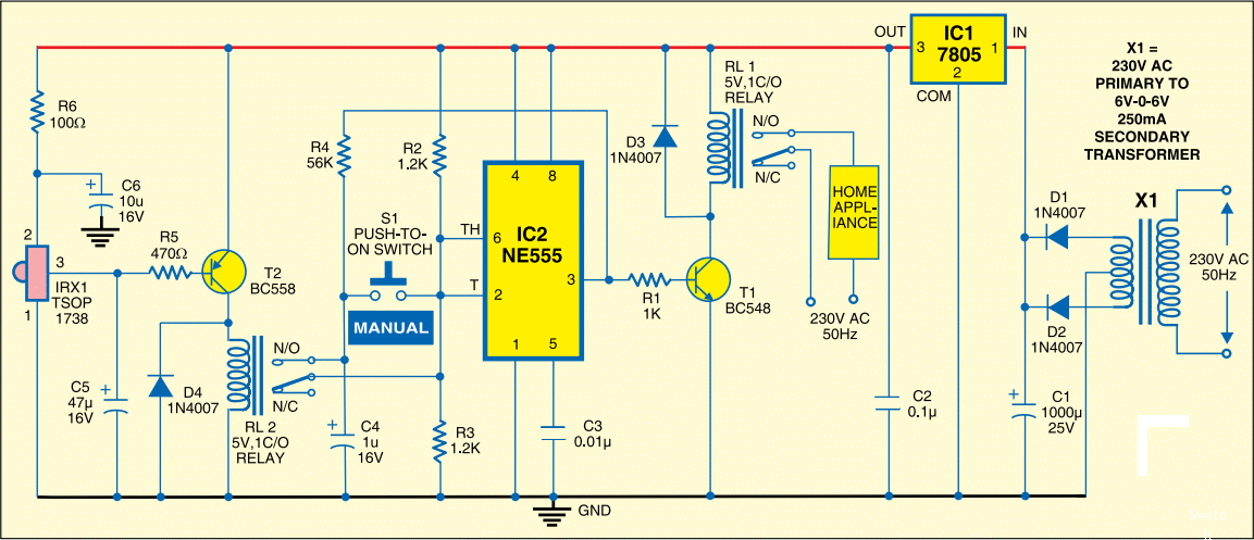
This circuit is designed to switch on/off any home or industrial appliance by using the TV/DVD remote controller. The circuit can be operated up to a distance of 5-10 metre depending on the remote used. The circuit consists of a step-down transformer X1 (6V-0-6V, 250mA secondary), 5V regulator 7805 (IC1), two 5V, 1 change-over (C/O) relay, a timer NE555 IC (IC2), an IR receiver module (IRX1 TSOP1738) and some discrete components. The circuit works on regulated 5V, which is derived from X1 and regulated by IC1. Home appliance is controlled either by pressing any key on the remote or by manually pressing switch S1 to ‘on’ state.


Home Appliance Controller Using TV Remote

The TV/DVD remote controller produces 38kHz frequency. The IR receiver module operates at this frequency. It is used to control relay RL2. The relay triggers IC2, which is wired in a bistable mode to control the home appliance connected at the contacts of relay RL1. Timer IC2 toggles relay RL1 when switch S1 is pressed momentarily. Threshold and trigger input pins 6 and 2 of IC2 are held at one-half of the power supply voltage (5V) by resistors R2 and R3. When output pin 3 of IC2 is high, capacitor C4 charges through resistor R4, and discharges when the output pin 3 is low.

When switch S1 is pressed, capacitor C4 voltage is applied to pins 2 and 6 of IC2, which causes the output of IC2 to change from low to high, or high to low. When switch S1 is released capacitor C4 charges or discharges to the original level at the output pin 3 of IC2. At normal condition, when InfraRed rays are not incident on TSOP1738, its output at pin 3 remains high. When any TV remote key is pressed, IR rays fall on the TSOP1738 and its output goes low. At the same time relay RL2 energises for a few seconds through pnp transistor T2 (BC558). The working of the circuit is simple.

Initially, when there are no IR rays falling on the IR receiver module, its output remains high. Transistor T2 is in cut-off condition. Relay RL2 does not energise and hence IC2 does not toggle. As a result home appliance connected at the contacts of relay RL1 remains switched off. When you press any remote key for the first time, IR receiver module’s output goes low and collector of the transistor T2 goes high. Relay RL2 energises and triggers IC2. Output of IC2 goes high and relay RL1 energises to switch on the appliance. Once relay RL1 is energised it remains in that state.

So the appliance which is connected at the contacts of relay RL1 remains switched on. Now when you press any remote key the second time, relay RL2 energises and re-triggers IC2. Output of IC2 goes low and relay RL1 de-energises to switch off the appliance. Once relay RL1 de-energises it remains in that state. So the home appliance remains off. This cycle repeats when any key of the TV remote is pressed to switch on/off the home appliance. Assemble the circuit on a general-purpose PCB and enclose in a suitable cabinet. Fix TSOP1738 and switch S1 on front side of the cabinet. Place transformer inside the cabinet and mains power cord at the back of the cabinet.

Touch switch using CD4011.


Description.
A simple touch switch circuit using CD4011 is given here. The IC CD4011 is wires as a flip flop here. The 9, 13 pins of the IC works as the set and reset contacts respectively.CMOS ICs like 4011 require requires a very low current for controlling its gates. Since the pins 9 and 13 are connected to the positive via resistors R1 and R2, the logic gates of the ICs will be in high state. When we touch through the points A, B the gates of the IC will be closed and the output becomes low. This switches ON the transistor Q1 and the relay gets activated. When we touch through the points C, D the gates again becomes high and switches the transistor OFF. This makes the relay OFF. Thus by touching through the contact points A,B and C,D the appliance connected through the relay can be switched On and OFF.
Circuit diagram with Parts list.

Notes.
  • The circuit can be assembled on a general purpose PCB.
  • The circuit can be powered from 12V DC.
  • The IC must be mounted on a holder.
  • The relay can be a 12 V, 200 Ohm SPDT relay.

Electromagnetic field sensor circuit


Notes.
This is a very simple circuit that can be used to sense electromagnetic radiations. The circuit can even detect hidden wrings. A 1mH inductor is used for sensing the electric field. The electric field will induce a small voltage in the sensor inductor and this induced voltage is amplified by the opamp.The headphone connect at the output of the opamp will give an audio indication of the electric field. For example, the electric field around a mains transformer can be heard as a 50 Hz hum. The POT R4 can be used to adjust the gain of the amplifier. By keeping the sensor inductor near to a telephone line, you can even hear the telephone conversations.
Circuit diagram with Parts list.
Notes.
  • Assemble the circuit on a general purpose PCB.
  • The circuit can be powered from a 9V PP3 battery.
  • It is better to have a radial type inductor for L1.
  • The POT R4 can be used to adjust the gain.
  • The switch S1 can be a slide type ON/OFF switch.
  • The IC1 must be mounted on a holder.
  • All electrolytic capacitors must be rated at least 15V.