Electronic Eye

 Electronic eye has much use in this electronic age. Also Known as magic eye. It can be used as an automatic guest indicator at the door, If fitted on the bottom of the door entrance. Once it is installed at the door there is no need to install a call bell. It can also be used at homes or in banks as a burglar alarm.

Fix the LDR to the wooden door or a locker to be protected in such a manner that when anybody tries to open it, a shadow falls on the LDR and the circuit gets activated and produce a pleasant sound through the buzzer.
This electronic eye circuit uses NOT gate from CMOS I.C CD 4049. CD 4049 contains 6 independent NOT gate in one package; we have used here (a) one only. NOT gate output goes high(1) when the input pin 3 is at lower then 1/3rd level of the supply voltage. Conversely the output goes low (0) when it is above 1/3rd level. So small change in the voltage of pin-2 is enough to change the level of output (pin-3) from 1 to 0 and 0 to 1. The output has only two states high and low and can not remain in any intermediate stage. It is powered by a 9V battery for portable use. The circuit is economic in power consumption. Pin 1 is connected to the positive supply and pin 8 is grounded.
To detect the present of an object we have used LDR and a source of light. LDR is a special type of resistance whose value depends on the brightness of the light which is falling on it. It has resistance of about 1 mega ohm when in total darkness, but a resistance of only about 5k ohms when brightness illuminated. It responds to a large part of light spectrum.
We have made a potential divider circuit with LDR and 220 KΩ resistance connected in series. We know that voltage is directly proportional to conductance so more voltage we will get from this divider when LDR is getting light and low voltage in darkness. This divided voltage is given to input of NOT gate.
As soon as LDR gets dark the voltage of input not gate drops 1/3rd of the supply voltage and pin 2 gets high and LED or buzzer which is connected to the output gets activated.
 Advantage of using Logic gate is that data can be easily send to other digital interface device ie one can easily fed data to computer using parallel port or for further processing .

Circuit Diagram :
electronic eye latest

Automatic Speed Controller for fans & Coolers

During summer nights, the temperature is initially quite high. As time passes, the temperature starts dropping. Also, after a person falls asleep, the metabolic rate of one?s body decreases. Thus, initially the fan/cooler needs to be run at full speed. As time passes, one has to get up again and again to adjust the speed of the fan or the cooler.The device presented here makes the fan run at full speed for a predetermined time. The speed is decreased to medium after some time, and to slow later on. After a period of about eight hours, the fan/cooler is switched off.Fig. 1 shows the circuit diagram of the system. IC1 (555) is used as an astable multivibrator to generate clock pulses. The pulses are fed to decade dividers/counters formed by IC2 and IC3. These ICs act as divide-by-10 and divide-by-9 counters, respectively. The values of capacitor C1 and resistors R1 and R2 are so adjusted that the final output of IC3 goes high after about eight hours.The first two outputs of IC3 (Q0 and Q1) are connected (ORed) via diodes D1 and D2 to the base of transistor T1. Initially output Q0 is high and therefore relay RL1 is energised. It remains energised when Q1 becomes high. The method of connecting the gadget to the fan/cooler is given in Figs 3 and 4. 

 Automatic Speed Controller for fans & Coolers
Circuit Diagram :  Automatic Speed Controller for fans & Coolers

 It can be seen that initially the fan shall get AC supply directly, and so it shall run at top speed. When output Q2 becomes high and Q1 becomes low, relay RL1 is turned ?off? and relay RL2 is switched ?on?. The fan gets AC through a resistance and its speed drops to medium. This continues until output Q4 is high. When Q4 goes low and Q5 goes high, relay RL2 is switched ?off? and relay RL3 is activated. The fan now runs at low speed.Throughout the process, pin 11 of the IC is low, so T4 is cut off, thus keeping T5 in saturation and RL4 ?on?. At the end of the cycle, when pin 11 (Q9) becomes high, T4 gets saturated and T5 is cut off. RL4 is switched ?off?, thus switching ?off? the fan/cooler.Using the circuit described above, the fan shall run at high speed for a comparatively lesser time when either of Q0 or Q1 output is high. At medium speed, it will run for a moderate time period when any of three outputs Q2 through Q4 is high, while at low speed, it will run for a much longer time period when any of the four outputs Q5 through Q8 is high.If one wishes, one can make the fan run at the three speeds for an equal amount of time by connecting three decimal decoded outputs of IC3 to each of the transistors T1 to T3. One can also get more than three speeds by using an additional relay, transistor, and associated components, and connecting one or more outputs of IC3 to it.
In the motors used in certain coolers there are separate windings for separate speeds. Such coolers do not use a rheostat type speed regulator. The method of connection of this device to such coolers is given in Fig. 4.
The resistors in Figs 2 and 3 are the tapped resistors, similar to those used in manually controlled fan-speed regulators. Alternatively, wire-wound resistors of suitable wattage and resistance can be used.

Flashy Christmas Lights

This simple and inexpensive circuit built around a popular CMOS hex inverter IC CD4069UB offers four sequential switching outputs that may be used to control 200 LEDs (50 LEDs per channel), driven directly from mains supply. Input supply of 230V AC is rectified by the bridge rectifiers D1 to D4. After fullwave rectification, the average output voltage of about 6 volts is obtained across the filter comprising capacitor C1 and resistor R5. This supply energises IC CD4069UB.
All gates (N1-N6) of the inverter have been utilised here. Gates N1 to N4 have been used to control four high voltage transistors T1 to T4 (2N3440 or 2N3439) which in turn drive four channels of 50 LEDs each through current limiting resistors of 10-kilo-o Base drive of transistors can be adjusted with the help of 10-kilo-ohm pots provided in their paths. Remaining two gates (N5 and N6) form a low frequency oscillator. The frequency of this oscillator can be changed through pot VR1. When pot VR1 is adjusted To get the best results, a low leakage, good quality capacitor must be used for the timing capacitor C2


Circuit Diagram :

electronics circuit diagrams fun electronics

TV remote control Blocker


Just point this small device at the TV and the remote gets jammed .   The circuit is self explanatory . 555 is wired as an astable multivibrator for a frequency of nearly 38 kHz. This is the frequency at which most of the modern TVs receive the IR beam . The transistor acts as a current source supplying roughly 25mA to the infra red LEDs. To increase the range of the circuit simply decrease the value of the 180 ohm resistor to not less than 100 ohm.
It is required to adjust the 10K potentiometer while pointing the device at your TV to block the IR rays from the remote. This can be done by trial and error until the remote no longer responds.


Circuit Diagram :

fun circuit hobby electronics circuit

JAM(Just A Minute) Circuit

This jam circuit can be used in quiz contests wherein any par- ticipant who presses his button (switch) before the other contestants, gets the first chance to answer a question. The circuit given here permits up to eight contestants with each one allotted a distinct number (1 to 8). The display will show the number of the contestant pressing his button before the others. Simultaneously, a buzzer will also sound. Both, the display as well as the buzzer have to be reset manually using a common reset switch. Initially, when reset switch S9 is momentarily pressed and released, all outputs of 74LS373 (IC1) transparent latch go ?high? since all the input data lines are returned to Vcc via resistors R1 through R8. All eight outputs of IC1 are connected to inputs of priority encoder 74LS147 (IC2) as well as 8-input NAND gate 74LS30 (IC3). The output of IC3 thus becomes logic 0 which, after inversion by NAND gate N2, is applied to latch-enable pin 11 of IC1. With all input pins of IC2 being logic 1, its BCD output is 0000, which is applied to 7-segment decoder/driver 74LS47 (IC6) after inversion by hex inverter gates inside 74LS04 (IC5). Thus, on reset the display shows 0. When any one of the push-to-on switches?S1 through S8?is pressed, the corresponding output line of IC1 is latched at logic 0 level and the display indicates the number associated with the specific switch. At the same time, output pin 8 of IC3 becomes high, which causes outputs of both gates N1 and N2 to go to logic 0 state. Logic 0 output of gate N2 inhibits IC1, and thus pressing of any other switch S1 through S8 has no effect. Thus, the contestant who presses his switch first, jams the display to show only his number. In the unlikely event of simultaneous pressing (within few nano-seconds difference) of more than one switch, the higher priority number (switch no.) will be displayed. Simultaneously, the logic 0 output of gate N1 drives the buzzer via pnp transistor BC158 (T1). The buzzer as well the display can be reset (to show 0) by momentary pressing of reset switch S9 so that next round may start. Lab Note: The original circuit sent by the author has been modified as it did not jam the display, and a higher number switch (higher priority), even when pressed later, was able to change the displayed number.

Circuit Diagram :

Gaming circuit jam circuit indicator

Automatic Street Light

An introduction:
Needs no manual operation for switching ON and OFF. When there is need of light it automatically switches ON. When darkness rises to a certain value then sensor circuit gets activated and switches ON and when there is other source of light i.e. day time, the street light gets OFF. The sensitiveness of the street light can also be adjusted. In our project we have used four L.E.D for indication of bulb but for high power switching one can connect Relay (electromagnetic switch) at the output of pin 3 of I.C 555. Then it will be possible to turn ON/OFF any electrical appliances connected all the way through relay.


Principle :
This circuit uses a popular timer I.C 555. I.C 555 is connected as comparator with pin-6 connected with positive rail, the output goes high(1) when the trigger pin 2 is at lower then 1/3rd level of the supply voltage. Conversely the output goes low (0) when it is above 1/3rd level. So small change in the voltage of pin-2 is enough to change the level of output (pin-3) from 1 to 0 and 0 to 1. The output has only two states high and low and can not remain in any intermediate stage. It is powered by a 6V battery for portable use. The circuit is economic in power consumption. Pin 4, 6 and 8 is connected to the positive supply and pin 1 is grounded. To detect the present of an object we have used LDR and a source of light.
LDR is a special type of resistance whose value depends on the brightness of the light which is falling on it. It has resistance of about 1 mega ohm when in total darkness, but a resistance of only about 5k ohms when brightness illuminated. It responds to a large part of light spectrum. We have made a potential divider circuit with LDR and 100K variable resistance connected in series. We know that voltage is directly proportional to conductance so more voltage we will get from this divider when LDR is getting light and low voltage in darkness. This divided voltage is given to pin 2 of IC 555. Variable resistance is so adjusted that it crosses potential of 1/3rd in brightness and fall below 1/3rd in darkness.
Sensitiveness can be adjusted by this variable resistance. As soon as LDR gets dark the voltage of pin 2 drops 1/3rd of the supply voltage and pin 3 gets high and LED or buzzer which is connected to the output gets activated.
Component used :
  1. 9v Battery with strip
  2. Switch
  3. L.D.R (Light Depending Resistance)
  4. I.C NE555 with Base
  5. L.E.D (Light Emitting Diode) 3 to 6 pieces.
  6. Variable Resistance of 47 KΩ
  7. P.C.B (Printed Circuit Board of 555 or Vero board.


COMPONENTS :
a) Battery: For 9v power supply we can use 6pcs dry cell or 6F22 9v single piece battery.
b)Switch:Any general purpose switch can be used. Switch is used as circuit breaker.
c) L.D.R: (Light Depending Resistance)
it is a special type of resistance whose value depends on the brightness of light which is falling on it. It has resistance of about 1mega ohm when in total darkness, but a resistance of only about 5k ohms when brightness illuminated. It responds to a large part of light spectrum.
d) L.E.D: (Light Emitting Diode)
A diode is a component that only allows electricity to flow one way. It can be thought as a sort of one way street for electrons. Because of this characteristic, diode are used to transform or rectify AC voltage into a DC voltage. Diodes have two connections, an anode and a cathode. The cathode is the end on the schematic with the point of the triangle pointing towards a line. In other words, the triangle points toward that cathode. The anode is, of course, the opposite end. Current flows from the anode to the cathode.
Light emitting diodes, or LEDs, differ from regular diodes in that when a voltage is applied, they emit light. This light can be red (most common), green, yellow, orange, blue (not very common), or infa red. LEDs are used as indicators, transmitters, etc. Most likely, a LED will never burn out like a regular lamp will and requires many times less current. Because LEDs act like regular diodes and will form a short if connected between + and -, a current limiting resistor is used to prevent that very thing. LEDs may or may not be drawn with the circle surrounding them.
e) Variable resistance: (Potentiometer)
Resistors are one of the most common electronic components. A resistor is a device that limits, or resists current. The current limiting ability or resistance is measured in ohms, represented by the Greek symbol Omega. Variable resistors (also called potentiometers or just “pots”) are resistors that have a variable resistance. You adjust the resistance by turning a shaft. This shaft moves a wiper across the actual resistor element. By changing the amounts of resistor between the wiper connection and the connection (s) to the resistor element, you can change the resistance. You will often see the resistance of resistors written with K (kilohms) after the number value. This means that there are that many thousands of ohms. For example, 1K is 1000 ohm,2K is 2000 ohm, 3.3K is 3300 ohm, etc. You may also see the suffix M (mega ohms). This simply means million. Resistors are also rated by their power handling capability. This is the amount of heat the resistor can take before it is destroyed. The power capability is measured in W (watts) Common wattages for variable
resistors are 1/8W, 1/4W, 1/2W and 1W. Anything of a higher wattage is referred to as a rheostat
f) PCB (Printed Circuit Board)
with the help of P.C.B it is easy to assemble circuit with neat and clean end products. P.C.B is made of Bakelite with surface pasted with copper track-layout. For each components leg, hole is made.
Connection pin is passed through the hole and is soldered.

automatic street light
Circuit Diagram

WORKING:
When light falls on the LDR then its resistance decreases which results in increase of the voltage at pin 2 of the IC 555. IC 555 has got comparator inbuilt, which compares between the input voltage from pin2 and 1/3rd of the power supply voltage. When input falls below 1/3rd then output is set high otherwise it is set low. Since in
brightness, input voltage rises so we
obtain no positive voltage at output of pin 3 to drive relay or LED, besides in poor light condition we get output to energize.

Precautions:
a) Use a Sensitive LDR. You can test it using a multimeter.
b) I.C should not be heated too much while soldering, excess heat can destroy it. For safety and easy to replace, use of I.C base is suggested. While placing the I.C pin no 1 should be made sure at right hole.
c) Opposite polarity of battery can destroy I.C so please check the polarity before switching ON the circuit. One should use diode in series with switch for safety since diode allows flowing current in one direction only.
d) L.E.D glows in forward bias only so incorrect polarity of L.E.D will not glow. Out put voltage of our project is 7.3 volt therefore 4 LED in series can be easily used with out resistance.
e) Each component should be soldered neat and clean. We should check for any dry soldered.
f) LDR should be so adjusted that it should not get light from streetlight itself.

Clap Switch


Here is a Hobby Circuit for electronics hobbyists that can switch on & off a light, Fan, Radio etc. by the sound of clap. The sound of clap is received by a small microphone that is shown biased by resistor R1 in the circuit. The microphone changes sound wave in to electrical wave which is further amplified by Q1. Transistor Q1 is used as common emitter circuit to amplify weak signals received by the microphone. Amplified output from the collector of transistor Q1 is then feed to the Bistable Multivibrator circuit also known as flip-flop circuit.
    Flip flop circuit is made by using 2 Transistor, in our circuit Q2&Q3. In a flip-flop circuit, at a time only one transistor conduct and other cut off and when it gets a trigger pulse from outside source then first transistor is cutoff and 2nd transistor conducts. Thus output of transistor is either logic-0 or logic-1 and it remains in one state 0 or 1 until it gets trigger pulse from outer source.
    The pulse of clap which is a trigger for flip-flop which makes changes to the output which is complementary (reverse). Output of flip-flop which is in the low current form is unable to drive relay directly so we have used a current amplifier circuit by using Q4 which is a common emitter circuit. Output of Q4 is connected to a Relay (Electromagnetic switch) which works like a mechanical switch and it becomes easy for connecting other electrical appliance.
    The relay contact is connected to the power line and hence turns on/off any electrical appliance connected all the way through relay.


 Clap Switch Part List:- 

Resistors
R1=15KΩ, R5,R6=1.5KΩ
R2,R11,R12=2.2MΩ, R13=2.2KΩ
R3=270KΩ, R4=3.3KΩ
R7,R8=10KΩ, R9,R10=27KΩ
Capacitors
C1=1000µf/16v
C2=.01µf,C3,C4=.047µf
Semi Conductors
Q1,Q2,Q3= BC548
D2,D3,D4= IN 4148
D1,D5=IN 4007, Q4=BC368
Misc
T1=12v/500mA Transformer
Mic= Condenser Microphone
K1= 12V Relay, B1= Bulb or Load

Home Appliance Controller Using TV Remote


Switch home or industrial appliance On/Off with TV remote control

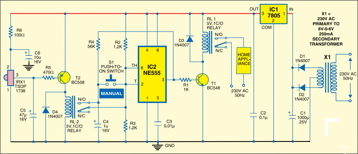
This circuit is designed to switch on/off any home or industrial appliance by using the TV/DVD remote controller. The circuit can be operated up to a distance of 5-10 metre depending on the remote used. The circuit consists of a step-down transformer X1 (6V-0-6V, 250mA secondary), 5V regulator 7805 (IC1), two 5V, 1 change-over (C/O) relay, a timer NE555 IC (IC2), an IR receiver module (IRX1 TSOP1738) and some discrete components. The circuit works on regulated 5V, which is derived from X1 and regulated by IC1. Home appliance is controlled either by pressing any key on the remote or by manually pressing switch S1 to ‘on’ state.


Home Appliance Controller Using TV Remote

The TV/DVD remote controller produces 38kHz frequency. The IR receiver module operates at this frequency. It is used to control relay RL2. The relay triggers IC2, which is wired in a bistable mode to control the home appliance connected at the contacts of relay RL1. Timer IC2 toggles relay RL1 when switch S1 is pressed momentarily. Threshold and trigger input pins 6 and 2 of IC2 are held at one-half of the power supply voltage (5V) by resistors R2 and R3. When output pin 3 of IC2 is high, capacitor C4 charges through resistor R4, and discharges when the output pin 3 is low.

When switch S1 is pressed, capacitor C4 voltage is applied to pins 2 and 6 of IC2, which causes the output of IC2 to change from low to high, or high to low. When switch S1 is released capacitor C4 charges or discharges to the original level at the output pin 3 of IC2. At normal condition, when InfraRed rays are not incident on TSOP1738, its output at pin 3 remains high. When any TV remote key is pressed, IR rays fall on the TSOP1738 and its output goes low. At the same time relay RL2 energises for a few seconds through pnp transistor T2 (BC558). The working of the circuit is simple.

Initially, when there are no IR rays falling on the IR receiver module, its output remains high. Transistor T2 is in cut-off condition. Relay RL2 does not energise and hence IC2 does not toggle. As a result home appliance connected at the contacts of relay RL1 remains switched off. When you press any remote key for the first time, IR receiver module’s output goes low and collector of the transistor T2 goes high. Relay RL2 energises and triggers IC2. Output of IC2 goes high and relay RL1 energises to switch on the appliance. Once relay RL1 is energised it remains in that state.

So the appliance which is connected at the contacts of relay RL1 remains switched on. Now when you press any remote key the second time, relay RL2 energises and re-triggers IC2. Output of IC2 goes low and relay RL1 de-energises to switch off the appliance. Once relay RL1 de-energises it remains in that state. So the home appliance remains off. This cycle repeats when any key of the TV remote is pressed to switch on/off the home appliance. Assemble the circuit on a general-purpose PCB and enclose in a suitable cabinet. Fix TSOP1738 and switch S1 on front side of the cabinet. Place transformer inside the cabinet and mains power cord at the back of the cabinet.

230V White LED Lamp


230V White LED Lamp

Did it ever occur to you that an array of white LEDs can be used as a small lamp for the living room? If not, read on. LED lamps are available ready-made, look exactly the same as standard halogen lamps and can be fitted in a standard 230-V light fitting. We opened one, and as expected, a capacitor has been used to drop the voltage from 230 V to the voltage suitable for the LEDs. This method is cheaper and smaller compared to using a transformer. The lamp uses only 1 watt and therefore also gives off less light than, say, a 20 W halogen lamp. The light is also somewhat bluer. The circuit operates in the following manner: C1 behaves as a voltage dropping ‘resistor’ and ensures that the current is not too high (about 12 mA).

The bridge rectifier turns the AC voltage into a DC voltage. LEDs can only operate from a DC voltage. They will even fail when the negative voltage is greater then 5 V. The electrolytic capacitor has a double function: it ensures that there is sufficient voltage to light the LEDs when the mains voltage is less than the forward voltage of the LEDs and it takes care of the inrush current peak that occurs when the mains is switched on. This current pulse could otherwise damage the LEDs. Then there is the 560-ohm resistor, it ensures that the current through the LED is more constant and therefore the light output is more uniform.

There is a voltage drop of 6.7 V across the 560-Ω resistor, that is, 12 mA flows through the LEDs. This is a safe value. The total voltage drop across the LEDs is therefore 15 LEDs times 3 V or about 45 V. The voltage across the electrolytic capacitor is a little more than 52V. To understand how C1 functions, we can calculate the impedance (that is, resistance to AC voltage) as follows: 1/(2π·f·C), or: 1/ (2·3.14·50·220·10-9)= 14k4. When we multiply this with 12 mA, we get a voltage drop across the capacitor of 173 V. This works quite well, since the 173-V capacitor voltage plus the 52-V LED voltage equals 225 V. Close enough to the mains voltage, which is officially 230 V.


Circuit Diagram


Electronic mosquito repeller


Description.
Here is the circuit diagram of an ultrasonic mosquito repeller.The circuit is based on the theory that insects like mosquito can be repelled by using sound frequencies in the ultrasonic (above 20KHz) range.The circuit is nothing but a PLL IC CMOS 4047 wired as an oscillator working at 22KHz.A complementary symmetry amplifier consisting of four transistor is used to amplify the sound.The piezo buzzer converts the output of amplifier to ultrasonic sound that can be heard by the insects.
Circuit diagram with Parts list.

Notes.
  • Assemble the circuit on a general purpose PCB.
  • The circuit can be powered from 12V DC.
  • The buzzer can be any general purpose piezo buzzer.
  • The IC1 must be mounted on a holder.